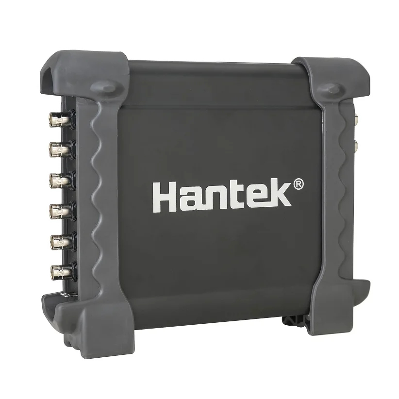
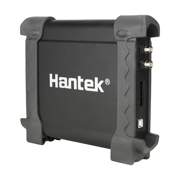
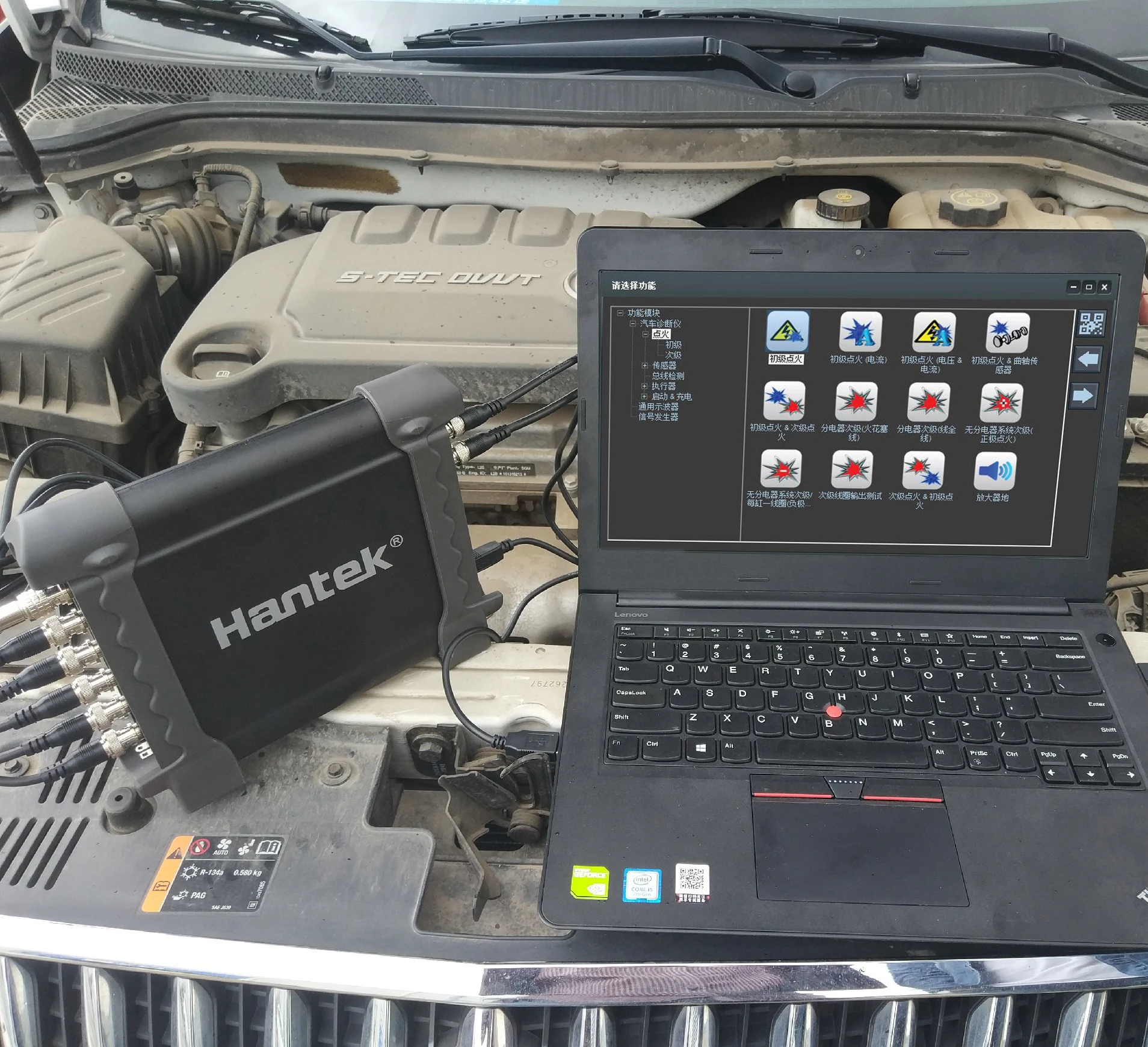
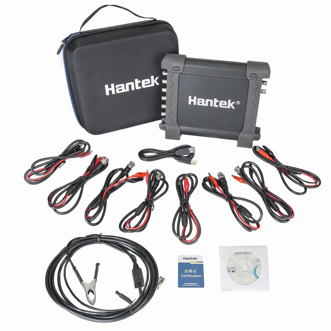
Hantek 1008C 8 Channels Oscilloscope Vehicle Testing Automotive Diagnostic Equipment USB Automotive Oscilloscope
-
Supplier: Shenzhen Kuaiqu Electronic Co., Ltd. -
Region: Guangdong, China -
Contact: Mr James Zhang -
Price: $76.91 / >=2 pieces -
Min. Order: 2 pieces
Product details
| Name: | PC USB Oscilloscope; | Payment: | TT; |
| Channel: | 8CH; | Selling Units: | Single item; |
| MOQ: | 1; | Single package size: | 20X25X15 cm; |
| keywords: | hantek 1008C; | Input Impedance: | Resistance: 1MΩ; |
| Product Name: | hantek automotive oscilloscope; | Input Sensitivity: | 10mV/div to 5V/div; |
| Warranty: | 1 Year; | Single gross weight: | 2.0 KG; |
| Brand Name: | Hantek; | Model Number: | Hantek1008C; |
| Type: | 8 channels oscilloscope for vehicle testing; | Place of Origin: | China; |
| Color: | Picture; |
Hantek 1008C 8 Channels Oscilloscope Vehicle Testing Automotive Diagnostic Equipment USB Automotive Oscilloscope
| Vehicle Diagnosis | Vehicle Diagnostic Function | Ignition | Primary Ignition (Voltage) |
| Primary Ignition(current) | |||
| Primary Ignition(Voltage& Current) | |||
| Primary Ignition (Crankshaft Senser) | |||
| Primary Ignition&SecondaryIgnition | |||
| Secondary | Secondary Ignition Distributor Type (Plug Lead) | ||
| Secondary Ignition Distributor Type (King Lead) | |||
| Secondary DIS (Positive-fired) | |||
| Secondary DIS or CPC (Negative-fired)) | |||
| Secondary Coil Output Diagnosis | |||
| Secondary Ignition&Primary Ignition | |||
| Sensors | Air Flow Meter | Air Flow Meter (Hot Wire) | |
| Air Flow Meter (Air Vane) | |||
| Air FlowSensor (BOSCH Diesel) | |||
| Air Intake PressureSensor (BOSCH Diesel) | |||
| Camshaft | Camshaft (Inductive) | ||
| Camshaft (AC Excited) | |||
| Camshaft (Hall Effect) | |||
| Camshaft (BOSCH Common Rail Diesel) | |||
| Crankshaft | Crankshaft Inductive Running | ||
| Crankshaft Inductive Cranking | |||
| Crankshaft Hall Effect | |||
| Crankshaft Sensor &Primary Ignition | |||
| Distributor | Distributor Pick-up (Hall Effect) | ||
| Distributor Inductive Pick-up Cranking | |||
| Distributor Inductive Pick-up Running | |||
| Lambda Sensors | Lambda Sensor Titania | ||
| Lambda Sensor Zirconia | |||
| Lambda Sensor Zirconia Pre & Post cat | |||
| Throttle Position | Throttle Position Potentiometer | ||
| Throttle Position Switch | |||
| Throttle Pedal Switch (Bosch Diesel) | |||
| ABS Digital Speed Sensor | |||
| ABS Analog Speed Sensor | |||
| Coolant Temperature (5V) | |||
| Coolant Temperature (GM/Vauxhall Simtec | |||
| Crash Sensor | |||
| MAP Analog | |||
| MAP Digital | |||
| Hall Effect Road Speed Sensor | |||
| Accelerator Pedal (Bosch Diesel) | |||
| Bus Diagnosis | CAN Bus | CAN Bus Data View | |
| CAN Bus Signal Integrity | |||
| CAN Bus LH Long Capture | |||
| LIN Bus | LIN Bus | ||
| Engine | Petrol | Single-point Injector (Voltage) | |
| Single-point Injector (Current) | |||
| Multi-point Injector (Voltage) | |||
| Multi-point Injector (Current) | |||
| Injector Voltage & Current | |||
| Injector Current & Primary Ignition | |||
| Diesel | Common Rail Diesel (Current) | ||
| Injector Bosch CDi 3 (Current) | |||
| Injector Bosch Diesel (Idling) | |||
| Injector Bosch Diesel (Accelerating) | |||
| Diesel Glow Plugs | |||
| Electronic Fuel Pump | |||
| Carbon Canister Solenoid Valve | |||
| ERG Recirculation Solenoid Valve | |||
| Stepper Motor Example 1 | |||
| Stepper Motor Example 2 | |||
| Idle Speed Control Valve (Rotary) | |||
| Idle Speed Control Valve (Electromagmetic) | |||
| Throttle Servomotor (Idling) | |||
| Throttle Servomotor (Accelerating) | |||
| Bosch CDi3 Quantity Control Valve | |||
| Bosch CDi3 Pressure Regulator Valve | |||
| Variable-Speed Cooling Fan On | |||
| Variable-Speed Cooling Fan Off | |||
| Variable Camshaft Valve Timing | |||
| Startup & Charge | Charging Circuits | Charging Circuits Current/Voltage | |
| Charging Circuits Current/Voltage Starting 24V | |||
| Charging Circuits Current/Voltage Idling 24V | |||
| Charging Circuits Alternator AC Ripple/Diode Diagnosis | |||
| Relative Compression Petrol | |||
| Relative Compression Diesel | |||
| Starting Voltage Drop | |||
| General Oscilloscope | Model | Hantek1008C | |
| Analog Channel | 8 | ||
| Input Impedance | Resistance: 1MΩ | ||
| Input Sensitivity | 10mV/div to 5V/div | ||
| Input Coupling | DC | ||
| Resolution | 12 bits | ||
| Memory Depth | 4K | ||
| Max. Input | 400V (DC+AC Peak) | ||
| Real-Time Sampling Rate | 2.4MSa/s | ||
| Time BaseRange | 1ns/div to 20000s/div(1-2-5sequences) | ||
| Time Base Precision | ±50ppm | ||
| Trigger Source | CH1, CH2,CH3,CH4, CH5, CH6,CH7,CH8 | ||
| Trigger Mode | Edge | ||
| X-Axis Input | CH1 | ||
| Y-Axis Input | CH2 | ||
| Voltage Measurement | Vpp, Vamp, Vmax, Vmin, Vtop, Vmid, Vbase,Vavg, Vrms, Vcrms, Preshoot, Overshoot | ||
| Time Measurement | Frequency, Period, Rise Time, Fall Time, Positive Width, Negative Width, Duty Cycle | ||
| Cursors Measurement | Horizontal ,Vertical, Track, Auto Measure Modes | ||
| Waveform Signal Process | +,- , x,÷, FFT, Invert | ||
| Voltage Range | 10mV to 5V/div @ x 1 probe | ||
| 100mV to 50V/div @ x 10 probe | |||
| 10V to 5000V/div @ x 1000 probe | |||
| 100V to 50000V/div @ x 10000 probe | |||
| 200mV to 100V/div @ 20:1 | |||
| Current Range | 100mA to50.0A/div @ CC65(20A) | ||
| 1000mA to500.0A/div @ CC65(65A) | |||
| 1A to100.0A/div @ CC650(60A) | |||
| 1A to200.0A/div @CC1100(100A) | |||
| 10A to2000.0A/div @CC1100(1100A) | |||
| FFT | Rectangular, Hanning, Hamming, Blackman Window | ||
| Math | Addition, subtraction, multiplication, division | ||
| Interface | USB 2.0(Full Speed) | ||
| Programmablesignal generator | Channel | 8CH | |
| Output Level | LVTTL | ||
| Frequency Range | 0-250kHz | ||
Our Services

VIEW MORE
You may like
-
Oscilloscope Hantek Dso2c15 Channel 2 Channel 150mhz 1gsa/s Sampling Rate Economical Dual Channel Digital Storage Oscilloscope

-
P6100 Oscilloscope Cost 1x 10x 100mhz Oscilloscope Digital Oscilloscope Portable 10:1 Switchable Oscilloscope Probe with Accessories

-
CEM DT-9989 0.025% DCV Accuracy Real-Time Sampling Rate Full PC Calibrated Handheld Oscilloscope Digital Professional Multimeter

-
Handheld oscilloscope DIY KIT

-
Fully Assembled Digital Oscilloscope 2.4" TFT LCD Display with Alligator Probe Test Clip for DSOO138 Oscilloscope

-
New Digital Oscilloscope 2023 Handheld LCR Oscilloscope 2 in 1 Transistor Tester DSO-TC2 PWM Square Wave Output Oscilloscope

-
FNIRSI DSO-TC3 10MS/s 500kHz Bandwidth Support Diode PWM Out Transistor LCR Signal Generator Digital Oscilloscope with P6100

-
Digital Super Phosphor 500MHz Bandwidth, Four Channels, 4GS/s Sample Rate, USB Communications Oscilloscope

-
MCP DQ2000Y - Digital Super Phosphor Oscilloscope 4 Channel Oscilloscope Digital 100MHz

-
Uni-t Low price oscilloscope portable digital oscilloscope oscilloscope

Other Products
-
 $46.00 / piece
 -
 $10.00 / piece
 -
 $106.60 / piece
 -
 $5.80 / piece
 -
 $42.00 / unit
 -
 $166.10 / piece
 -
 $301.00 / piece
 -
 $150.00 / piece
 -
 $75.00 / piece
 -
 $36.36 / unit


